
Can datasheet‑compliant CKTB500‑9‑100 variable vacuum capacitors sustain stable RF‑performance under long‑duration real‑system cyclic operating stresses?
Njhighhope implements multi‑layer pre‑qualification workflows for Variable Vacuum Capacitor CKTB500/9/100, combining high‑cycle mechanical‑tuning endurance testing, RF‑power thermal‑cycling ageing and transit‑shock environmental‑simulation, uncovering datasheet‑hidden performance‑risks well before component batches ship to high‑power RF‑equipment OEM projects.
1. High‑cycle mechanical‑tuning endurance evaluation exposes bellows‑and‑screw‑drive progressive‑wear risks
Laboratory sample‑testing executes limited adjustment cycles for parameter‑verification. In real‑world RF matching‑network installations, vacuum capacitors undergo frequent automated or manual capacitance‑tuning over thousands of operating‑hours. Repeated back‑and‑forth adjustment imposes cyclic stress upon metal bellows assemblies and precision drive‑screw mechanisms. Inadequate material‑temper or marginal machining‑quality produces incremental mechanical‑play. Over time, positional hysteresis expands; capacitance readout deviates from actual adjusted value, disrupting closed‑loop impedance‑matching control. Static single‑point lab‑measurement cannot expose slow‑developing mechanical‑hysteresis drift. Njhighhope subjects finished CKTB500‑9‑100 assemblies to large‑quantity full‑range tuning‑cycle lab‑simulation. Post‑cycling capacitance‑hysteresis measurement validates mechanical‑system long‑term stability, reducing matching‑control‑instability risk for dynamically‑tuned RF‑power systems.
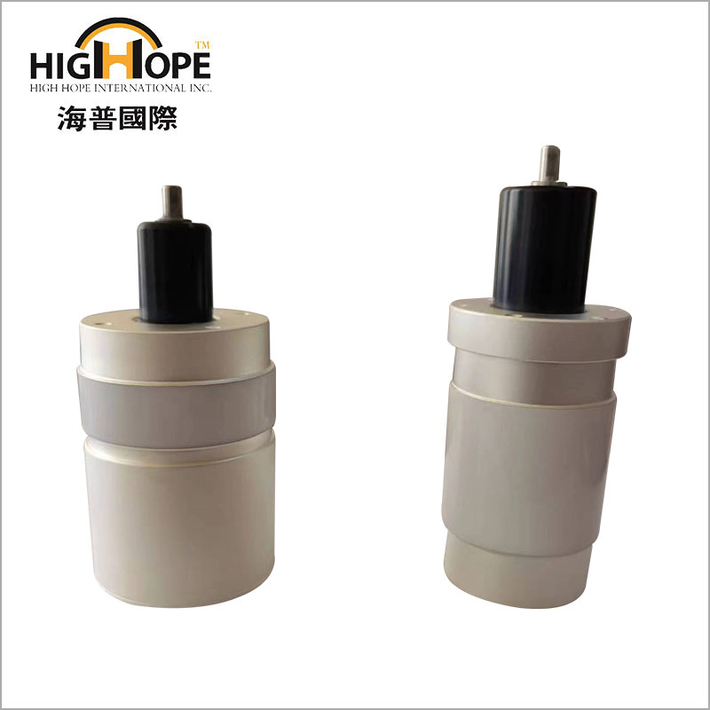
2. RF‑power thermal‑cycling ageing uncovers electrode‑surface conditioning‑degradation hazards
Standard datasheet testing often applies DC or low‑level RF‑signal excitation at constant ambient‑temperature. Actual field‑operation subjects vacuum‑capacitor internal electrodes to cyclic heat‑rise under high‑RF‑power loading followed by passive cool‑down periods. Repeated thermal‑expansion‑contraction cycles modify electrode‑surface micro‑morphology; residual adsorbed‑gas outgassing accumulates inside vacuum envelope. This gradually lowers effective high‑power RF‑breakdown threshold, triggering sporadic internal arcing events, even though cold‑state DC withstand‑voltage fully satisfies datasheet figures. Njhighhope runs cyclic high‑power RF‑thermal‑ageing simulation replicating real‑equipment load‑duty‑cycles. Post‑ageing high‑power‑RF‑hold‑off‑testing screens units with degraded electrode‑surface condition, mitigating in‑service intermittent‑arcing‑related RF‑system‑shut‑down probability.
3. Combined transit‑shock‑vibration simulation identifies hidden micro‑leak initiation pathways
Lab‑test samples are handled with extreme care under workshop‑conditions. Cross‑border land‑and‑sea logistics expose finished vacuum‑capacitor units to multi‑axis vibration and occasional mechanical‑shock. Ceramic‑to‑metal brazed sealing joints represent critical stress‑concentration points. Subtle micro‑cracks may initiate at braze interfaces during transit without immediate catastrophic vacuum‑loss. Micro‑leaks progress slowly after installation; vacuum‑degree degrades month‑by‑month, bringing gradual deterioration of RF‑withstand‑performance. Visual inspection and initial bench vacuum‑testing at incoming‑goods stage often miss incipient micro‑leak defects. Njhighhope executes combined vibration‑shock transit‑simulation according to component‑transport industry‑norms. Post‑simulation fine‑leak‑detection screening filters marginal‑seal‑integrity units before shipment, preventing slow‑vacuum‑degradation incidents in end‑user RF‑installations.
4. Condensation‑exposure assessment guards against external ceramic‑insulator surface‑tracking risk
Lab‑evaluation maintains components within dry constant‑humidity environments. Some field‑deployed RF‑equipment cabinets encounter diurnal temperature‑swing, creating temporary dew‑condensation upon external ceramic insulator surfaces. Under high RF‑potential, contaminated damp ceramic surfaces develop conductive surface‑tracking paths. This creates external flash‑over events independent of internal vacuum‑quality. Pure internal vacuum‑performance tests give no indication of this external‑insulator failure‑mode. Njhighhope carries out humidity‑condensation environmental‑exposure testing for CKTB500‑9‑100 assemblies. Post‑exposure RF‑flash‑over‑voltage measurement validates insulator‑surface robustness under dew‑forming‑conditions, lowering unplanned flash‑over‑triggered equipment‑protective‑tripping in non‑climate‑controlled cabinet‑installations.
5. Multi‑frequency RF‑characterisation reveals off‑nominal‑frequency Q‑factor drift risks
Datasheet Q‑factor values are typically captured at one reference‑test‑frequency point. Real‑RF‑systems operate across wide frequency bands during tuning‑adjustment. Variations of internal residual‑inductance and dielectric‑loss shift actual Q‑performance away from single‑point‑datasheet values at off‑nominal operating‑frequencies. If system‑design relies exclusively upon single‑frequency datasheet‑figures, real‑circuit loop‑loss rises, reducing overall RF‑power‑transfer‑efficiency. Njhighhope performs multi‑frequency Q‑factor mapping across the capacitor’s full capacitance‑adjustment‑range. Multi‑point‑RF‑characterisation datasets are provided to OEM customers, supporting more accurate RF‑matching‑network simulation and avoiding unexpected efficiency‑loss after system commissioning.
6. Serial‑lot traceable component‑validation‑dossiers satisfy RF‑equipment third‑party‑qualification audit requirements
Global broadcast‑and‑industrial‑RF‑equipment third‑party‑qualification workflows demand component‑level supporting‑test‑documentation. Isolated prototype‑sample datasheet‑reports cannot represent serial‑production‑batch unit‑performance. Without lot‑specific English‑language validation‑archives covering mechanical‑endurance, RF‑thermal‑ageing and leak‑detection results, finished RF‑systems risk qualification‑hold‑up. Njhighhope compiles unified project‑tied component‑test‑dossiers for CKTB500‑9‑100 orders. Complete traceable archives simplify system‑level certification workflows for RF‑transmitter and plasma‑equipment integrators without additional third‑party‑component‑re‑testing expenditure.
Send Inquiry


X
We use cookies to offer you a better browsing experience, analyze site traffic and personalize content. By using this site, you agree to our use of cookies.
Privacy Policy